
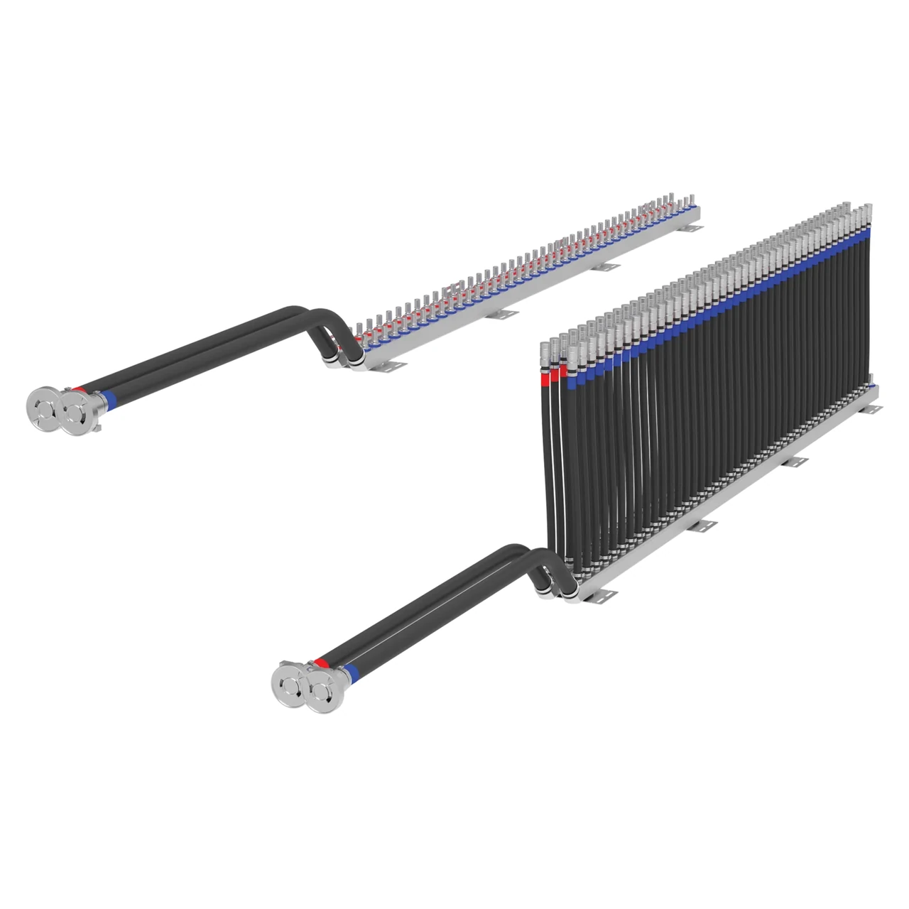
Map the flow path
Number each supply and return port on a controlled drawing. State the connected branch, connection type, orientation and planned flow for each port. Identify spare or service ports explicitly.
Define the rack envelope
Show mounting datums, clearance to hoses and connectors, removal path and service access. List included valves, sensors, drains or filters separately so the quoted assembly boundary is clear.
Specify measurable acceptance
Give fluid properties and temperature, total and branch flow, inlet conditions and allowable pressure drop with the corresponding operating point. Set inspection, cleanliness, leak-test and documentation requirements for the actual configuration.
Quote Request Checklist
- System position and rack envelope
- Port map and connection interfaces
- Flow distribution and pressure-drop target
- Attached components, inspection, and test scope
Related reading
If only some parts of a loop will be replaced after a leak, see What to send after a loop leak when only some liquid-cooling parts will be replaced.
A named hose-whip manifold example, not a stock confirmation, is nVent HOFFMAN RCM42001H.
Official-catalog manifold and sensor examples, not a stock list: SMC PF3WB, SMC PF3WC, and SMC PF3W720-04-A.
Official manufacturer-table node-manifold examples, not a stock list or an interchange statement: BEEHE GB200 dual-branch, BEEHE Rubin five-branch, and BEEHE MGX multi-branch.
Official manufacturer fact sheets can also be used as specification examples when a drawing is prepared (these links are not a stock statement): the official GF In-Rack Manifold fact-sheet series is summarized on GF PVDF in-rack liquid-cooling manifold, and the official KUNGFLEX English liquid-cooled-manifold page is summarized on KUNGFLEX stainless supply-and-return rack manifold pair.